
Introduction
Accuracy is critical in custom manufacturing. Even a small error in a dimension, hole position, material specification, or component design can lead to production delays, rejected parts, additional costs, and unnecessary rework.
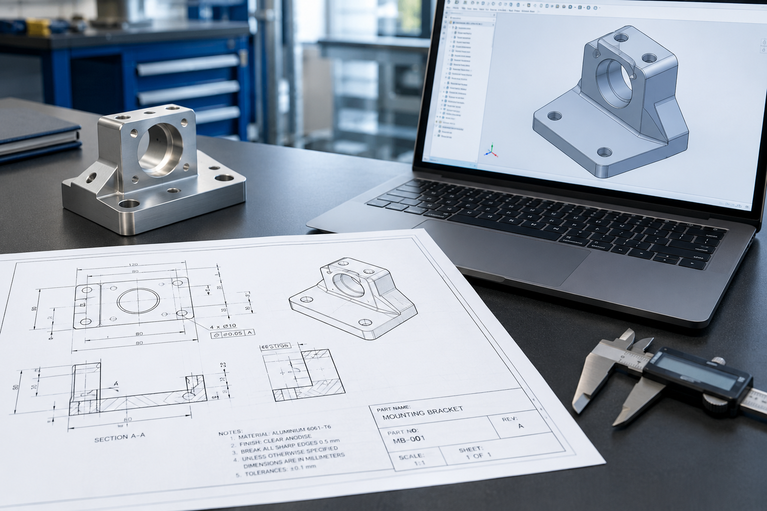
For engineers and businesses preparing designs for production, CAD drawings for manufacturing provide a structured way to communicate technical requirements before manufacturing begins. They translate design concepts into clear, detailed engineering information that machinists, fabricators, production teams, and other stakeholders can interpret.
Computer-Aided Design (CAD) supports the development of precise 2D engineering drawings and 3D models, helping teams identify potential issues, clarify component geometry, and coordinate the transition from design to production.
Professional CAD drafting services can also help businesses prepare technical drawings that communicate dimensions, tolerances, materials, and other manufacturing requirements more clearly.
In this article, we explore how CAD drawings improve manufacturing accuracy, reduce errors, support production planning, and help businesses move from design concepts to manufactured components more efficiently.
What Are CAD Drawings for Manufacturing?
CAD drawings for manufacturing are technical drawings or digital design documents created using Computer-Aided Design software to communicate how a component or assembly should be manufactured.
They can include dimensions, tolerances, material specifications, hole locations, surface finish requirements, geometric details, and other information relevant to production.
Manufacturing drawings may include:
2D engineering drawings: Orthographic views, dimensions, sections, notes, and detailed component specifications.
3D CAD models: Digital representations of component geometry that help communicate shape, features, and assembly relationships.
Assembly drawings: Information showing how individual components fit together.
Detail drawings: Manufacturing information for individual parts.
Manufacturing notes: Material, finishing, thread, and other production requirements.
The appropriate drawing format depends on the component, manufacturing process, and information the production team needs.
For example, a CNC-machined component may require detailed dimensions, tolerances, hole specifications, and material information. A fabricated steel assembly may need overall dimensions, individual part details, joint locations, and welding requirements where applicable.
The goal is simple: ensure that everyone involved in production understands the design intent and the requirements that must be met.
1. How CAD Drawings Improve Manufacturing Accuracy
Manufacturing accuracy depends on clear specifications, suitable processes, capable equipment, and effective quality control. CAD drawings support this process by reducing ambiguity and providing a consistent technical reference.
Clear and Precise Dimensions
One of the most important benefits of CAD drawings for manufacturing is the ability to define component dimensions clearly.
A technical drawing can specify lengths, widths, thicknesses, diameters, hole positions, angles, and other critical measurements. This information helps production teams manufacture parts according to the approved design rather than relying on estimates or assumptions.
For example, a custom-machined mounting plate may require several holes to align with an existing assembly. Clearly dimensioned hole centres and spacing help the machinist understand the required positions and reduce the risk of incorrect drilling or machining.
Accurate drawings do not automatically guarantee accurate parts, but they establish the dimensional requirements against which manufactured components can be produced and checked.
Better Control of Tolerances
Tolerances define the permitted variation in a dimension or feature. They are particularly important when components must fit together, move correctly, or interface with existing equipment.
CAD drawings allow engineers to specify tolerances where necessary, helping manufacturing teams understand which dimensions require tighter control.
For example, a shaft that fits into a bearing may require a defined dimensional relationship to achieve the intended fit. If the drawing does not communicate the necessary tolerance, the resulting component may be too tight, too loose, or unsuitable for the application.
Appropriate tolerances should be based on the component's function, manufacturing capability, and inspection requirements. Overly tight tolerances can increase manufacturing costs without providing a practical benefit.
Consistent Technical Communication
A properly prepared engineering drawing provides a common reference for designers, machinists, fabricators, procurement teams, and quality personnel.
Instead of interpreting separate sketches, informal messages, or conflicting dimensions, stakeholders can work from a controlled drawing revision.
This improves consistency throughout the design-to-production workflow and helps teams identify the exact specifications that apply to a component.
2. How CAD Drafting Services Help Reduce Manufacturing Errors
Errors are often introduced when design information is incomplete, inconsistent, or difficult to interpret. Professional CAD drafting services help organise technical information and make manufacturing requirements easier to communicate.
Reducing Dimensioning Mistakes
Incomplete dimensions can force production teams to estimate measurements or request clarification before proceeding.
A well-prepared drawing identifies the dimensions required to define a component, including important features and relationships between them.
For example, a fabricated bracket may need clearly defined hole spacing, bend dimensions, plate thickness, and overall geometry. Missing information could result in a part that cannot be installed as intended.
CAD drafting helps make these requirements visible before production begins.
Identifying Design Conflicts Earlier
CAD models can help engineers review component geometry before committing to manufacturing.
Depending on the software and modelling workflow, designers may inspect clearances, identify overlapping features, review assembly relationships, and detect potential interference between components.
Consider a custom enclosure with mounting brackets and internal components. A 3D model can help reveal whether the brackets interfere with other parts or whether sufficient space has been allowed for assembly.
Finding such issues during design is generally easier than correcting them after components have been machined or fabricated.
Managing Drawing Revisions
Design changes are common in custom manufacturing. A hole may move, a plate thickness may change, or a component may need a revised interface.
If an outdated drawing remains in circulation, production teams may manufacture parts using superseded specifications.
A controlled CAD drawing workflow helps identify revisions, communicate approved changes, and reduce the risk of manufacturing from incorrect information.
Businesses should use clear revision identifiers, approval processes, and document-control practices to ensure production teams have the current authorised drawing.
3. The Role of 2D CAD Drawings and 3D CAD Models in Production
Both 2D drawings and 3D models can contribute to manufacturing accuracy, but they serve different purposes.
2D CAD Drawings for Manufacturing
2D CAD drawings communicate dimensions, views, sections, tolerances, notes, and other technical requirements in a structured format.
They are particularly useful for specifying individual components, communicating fabrication details, and providing a reference for manufacturing and inspection.
For CNC machining, a 2D drawing can define critical dimensions and tolerances. For fabrication, it can communicate overall dimensions, material thickness, hole positions, and relevant joining details.
3D CAD Models for Visualisation and Design Validation
3D CAD models allow engineers to examine the shape and spatial relationships of components before production.
They can help communicate complex geometries, support assembly reviews, and provide digital geometry for compatible manufacturing workflows.
For example, a complex machined component may be easier to understand when the production team can review both the 3D model and its detailed 2D drawing.
However, a 3D model should not automatically be treated as a complete manufacturing specification. Critical dimensions, tolerances, materials, finishes, and other requirements may still need to be explicitly documented.
Why Combining 2D and 3D CAD Matters
Using 2D drawings alongside 3D models can provide both detailed manufacturing instructions and a clear visual understanding of the component.
The appropriate combination depends on the part, the manufacturing process, the production team's requirements, and the agreed technical documentation standard.
4. How CAD Drawings Support CNC Machining and Metal Fabrication
CAD drawings connect engineering design with practical manufacturing requirements. Their value becomes particularly clear when components need to be machined, cut, bent, welded, or assembled.
CNC Machining
CNC machining uses computer-controlled equipment to remove material and produce components to specified geometry.
CAD drawings help communicate critical dimensions, hole locations, threads, tolerances, and material requirements. Where suitable, compatible 3D CAD models can also support computer-aided manufacturing (CAM) programming.
For example, a custom-machined aluminium housing may require precise mounting holes, internal features, and defined mating surfaces. Clear drawings help the production team understand the intended geometry and the dimensions that must be verified.
The manufacturing result still depends on suitable tooling, programming, machine capability, material behaviour, setup, and inspection.
Waterjet Cutting
Waterjet cutting uses a high-pressure water stream, often with abrasive material, to cut profiles from suitable materials.
CAD geometry can help define the required cutting profile, including external contours and internal features. Clear technical information helps reduce ambiguity when preparing a part for cutting.
The drawing or model should account for material thickness, required dimensions, edge requirements, and any additional operations needed after cutting.
Metal Fabrication
Fabrication projects frequently involve multiple parts that must align during assembly.
CAD drawings can communicate component dimensions, plate thicknesses, hole positions, bend details, and assembly relationships. Depending on the project, they may also specify welding details and other joining requirements.
For a custom steel frame, for instance, clearly documented member lengths, connection locations, and overall dimensions help the fabrication team prepare and assemble components correctly.
By supporting machining, cutting, and fabrication workflows, CAD drawings help connect design intent with the requirements of the selected manufacturing process.
5. How CAD Drawings Reduce Rework, Waste, and Production Costs
Manufacturing errors can create costs beyond the price of replacing a component. They may involve wasted material, additional machine time, delayed deliveries, repeat inspections, and disruption to other production activities.
CAD drawings help reduce these risks by making requirements clearer before manufacturing begins.
Fewer Avoidable Production Corrections
When dimensions and specifications are clearly documented, production teams have a better reference for manufacturing and inspection.
This can reduce avoidable corrections caused by missing measurements, unclear notes, or inconsistent design information.
Better Material Planning
CAD geometry and drawings can support material planning by defining component dimensions, thicknesses, and profiles.
For cutting operations, suitable CAD data can also help production teams plan how parts fit within available material. Actual material savings depend on nesting, cutting allowances, machine constraints, and production quantities.
More Efficient Communication
Clear technical drawings can reduce repeated clarification between engineers and production teams.
When requirements are documented consistently, teams can resolve questions earlier, assess design changes more effectively, and coordinate manufacturing activities with fewer misunderstandings.
The financial benefit depends on the project, but preventing avoidable errors before production is generally more efficient than correcting them after manufacture.
6. What Should a Manufacturing-Ready CAD Drawing Include?
A manufacturing-ready drawing should communicate enough information for the intended production and inspection processes without unnecessary ambiguity.
Depending on the component, it may include:
Component identification: Part name, drawing number, revision, and relevant project references.
Dimensions: Overall measurements and the dimensions needed to define important features.
Tolerances: Permitted dimensional variation and any necessary geometric tolerances.
Material specifications: Material type and grade, where required.
Views and sections: Orthographic views, detail views, or sections that clarify component geometry.
Threads and hole details: Hole sizes, locations, thread specifications, and depths where applicable.
Surface finish requirements: Relevant finishing or surface texture specifications.
Manufacturing notes: Additional instructions needed for machining, cutting, fabrication, or assembly.
Revision information: The current approved revision and appropriate change records.
Not every component needs every item. The documentation should reflect the part's function, complexity, risk, and manufacturing method.
Engineers should also ensure that drawing dimensions are consistent, units are clear, and the document does not contain conflicting or redundant specifications.
7. When Should Businesses Use Professional CAD Drafting Services?
Professional CAD drafting services can be valuable when a business needs to convert concepts, sketches, legacy drawings, or design information into structured technical documentation for production.
Common situations include:
Preparing manufacturing drawings from an approved design.
Converting hand sketches or existing drawings into CAD format.
Developing 2D drawings and 3D models for custom components.
Updating drawings to reflect approved engineering changes.
Preparing clearer documentation for CNC machining or metal fabrication.
Reviewing drawing completeness before requesting a manufacturing quote.
For engineers and businesses without sufficient in-house drafting capacity, external CAD drafting support can help organise technical information and prepare documentation for the next production stage.
However, drafting and engineering design are not always the same service. Businesses should clarify whether they need drawing preparation, design development, engineering calculations, design validation, or formal approval. These activities have different responsibilities and may require appropriately qualified professionals.
8. How to Improve Your Design-to-Production Workflow
A reliable design-to-production workflow combines clear CAD documentation with review, approval, manufacturing planning, and quality checks.
A practical process includes the following steps:
Step 1: Define the requirements. Establish the component's function, material, operating conditions, interfaces, and performance needs.
Step 2: Develop the CAD design. Create or update the 2D drawings and 3D models needed to communicate the design.
Step 3: Review the design. Check dimensions, tolerances, clearances, material specifications, and assembly relationships.
Step 4: Confirm manufacturability. Review whether the design is suitable for the intended machining, cutting, fabrication, or assembly process.
Step 5: Approve and release documentation. Confirm the correct drawing revision and communicate the approved information to production.
Step 6: Manufacture and inspect. Produce the component using suitable processes and verify relevant characteristics against the approved specifications.
Step 7: Manage changes. Record approved revisions and ensure updated information reaches the people responsible for manufacturing and inspection.
Following this process helps businesses identify potential issues earlier, improve communication, and establish a consistent reference from design through to production.
Conclusion
CAD drawings for manufacturing play an important role in communicating technical requirements, improving dimensional clarity, and reducing avoidable errors in custom manufacturing.
Detailed 2D drawings, suitable 3D models, clear tolerances, appropriate material specifications, and controlled revisions help engineers and production teams work from consistent information. They also support CNC machining, waterjet cutting, metal fabrication, and other manufacturing processes.
However, CAD drawings are only one part of achieving a reliable manufacturing outcome. Suitable design decisions, capable equipment, process planning, skilled production teams, and effective inspection remain essential.
For businesses preparing designs for production, investing in clear technical documentation can help establish a stronger foundation for manufacturing accuracy and efficiency.
Need CAD drafting support for your next manufacturing project?
Bluewater Engineering offers CAD drawing and manufacturing-related services to support engineering requirements. Visit the CAD services page to learn more, or contact Bluewater Engineering to discuss your project.
Frequently Asked Questions (FAQs)
1. How do CAD drawings improve manufacturing accuracy?
CAD drawings improve manufacturing accuracy by clearly communicating dimensions, tolerances, material specifications, and component geometry. They provide a consistent technical reference for production and inspection, reducing ambiguity and helping teams identify potential design issues before manufacturing.
2. Why are CAD drafting services important for custom manufacturing?
CAD drafting services help convert design concepts, sketches, and existing technical information into structured manufacturing drawings. They can improve drawing clarity, document important specifications, and help engineers communicate requirements to machinists, fabricators, and production teams.
3. What is the difference between 2D CAD drawings and 3D CAD models?
2D CAD drawings communicate dimensions, views, tolerances, notes, and manufacturing requirements. 3D CAD models represent a component's geometry and spatial relationships. Used together where appropriate, they help explain both the detailed specifications and the overall shape of a component.
4. Can CAD drawings reduce manufacturing costs?
CAD drawings can help reduce avoidable costs by identifying missing information, clarifying specifications, and supporting design reviews before production. Potential savings include less rework, reduced material waste, and fewer delays, although actual results depend on the project and manufacturing process.
5. Are CAD drawings necessary for CNC machining?
Detailed CAD drawings are commonly used to communicate component dimensions, tolerances, materials, and other requirements for CNC machining. Compatible 3D models may also support CAM programming. The documentation required depends on the component and the agreed manufacturing workflow.
6. What information should a CAD drawing include for manufacturing?
A manufacturing drawing may include part identification, dimensions, tolerances, material specifications, views, hole and thread details, surface finish requirements, manufacturing notes, and revision information. The required details depend on the component and its intended application.
7. Can CAD drafting services help prepare an existing design for production?
Yes. CAD drafting services can help convert sketches or legacy drawings into CAD documentation, update approved designs, and prepare clearer technical drawings. The scope should be agreed in advance, particularly when engineering validation or formal design approval is also required.
8. How do CAD drawings support metal fabrication?
CAD drawings communicate component dimensions, plate thicknesses, hole locations, bend details, and assembly relationships. Where required, they can also include welding and joining details, helping fabrication teams understand how parts should be prepared and assembled.